With the increased concern for energy conservation and cleaner air, better control of the engine combustion process became necessary. Now, Oxygen Sensors are used in all internal combustion engine fuel control systems.
What Do These Sensors Do?
The Oxygen Sensor is used to adjust and maintain desired engine air/fuel mixtures to better control exhaust emissions and fuel economy.
Starting in the 1994 model year, federal regulations required that vehicles have an oxygen sensor in the exhaust system after the catalytic converter. This sensor checks the performance of the converter. It may also be used to aid in adjusting the engine air fuel ratio. If there are leaks in the exhaust system ahead of this sensor, it can cause improper emissions system performance. While oxygen sensors used behind the catalytic converter are very similar to the sensors used for engine control, their signals may not look the same.
Most automotive Oxygen Sensors are made of zirconia. This ceramic material will produce a voltage in response to the amount of unused oxygen in the exhaust stream. It does this by comparing the amount of oxygen in the exhaust to the amount of oxygen in the air. When the exhaust is lean (excess air), the sensor produces a low voltage (near zero volts). When the exhaust is rich (excess fuel), it produces a high voltage (up to one volt).
For the sensor to work correctly, it needs a good source of outside air for reference. It also needs temperatures of at least 260°C (500°F). Newer sensors contain an electric heater that helps them heat up faster and increases the element temperature above exhaust gas temperatures. Many heated sensors are waterproof and must receive outside reference air through the lead wires. Only a small amount of air is needed. However, the air path can become restricted by grease, dirt and other debris picked up while driving on roadways.
The ECM (Engine Control Module) compares the voltage from the Oxygen Sensor to the values programmed into it. If the air/fuel ratio is lean, it adds fuel. If the air/fuel ratio is rich, it subtracts fuel to keep the engine running at the desired point.
Sensor Types
Oxygen Sensors are divided into different types depending on the way they get heat for the element and by the way their air reference is protected. Most early oxygen sensors were of the unheated type. The exhaust gas provides the heat to bring the sensor element to operating temperature. Many newer sensors are of the heated type. An electric heater inside the sensor provides added heat to the zirconia element. This helps the element come up to temperature faster, operate better in colder running engines, give improved fuel control, and be less sensitive to contaminants. The heater power comes directly from the vehicle electrical system. It is usually turned on with the ignition switch. In some vehicles, relays may be used to turn the heater off and on under certain conditions.
Zirconia Oxygen Sensors only need a small amount of air to function properly. It is important, however, that these sensors be designed and located to obtain enough clean air for the sensing element if the sensor is to work accurately. Most unheated sensors have a rather open path to outside air. When sensors are in an area of the vehicle where they will not be splashed with water, very little shielding of the air reference is needed. Water Resistant sensors improve the ability of the sensor to withstand water splashes. Added shielding helps keep water out of the sensor while still making an easy path for air to get inside. Waterproof sensors do not allow water into the air reference path, even when submerged. Many of the waterproof sensors get the little air they need through their electrical wires.
Common Issues
Although designed for the life of the sensor, it is possible for electric heaters used in heated sensors to fail. The heater may break and become an open circuit, or it could become shorted to ground. If the heater fails, the sensor may become sluggish and will not perform well at low exhaust temperatures. If the heater circuit has a short to ground, it may blow a fuse. This can cause other items on the same circuit to become inoperative. Before assuming that the sensor is a problem, be sure electrical power is getting to the sensor and the short is not elsewhere in the vehicle wiring. A professional automotive technician can check the operation of the heater circuit while the sensor is still in the vehicle.
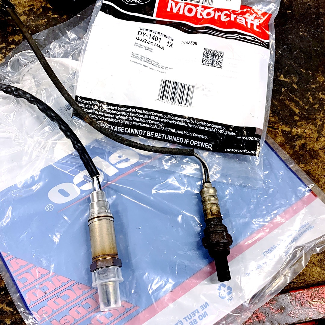
Heated oxygen sensors have two additional wires (4 wires total) when compared to earlier unheated versions. These connect to the vehicle electrical system and to the electric heater inside the sensor. The negative (-) signal wire of some heated sensors connects to the case of the sensor. In others, it does not. It is easy to determine if the negative wire is connected to the body of the sensor when the connection is visible on the outside. There is no easy way to tell when the connection is on the inside. To ensure the check engine light remains out in your vehicle following an oxygen sensor replacement, using the proper sensor is critical.
Oxygen Sensors Are Sensitive
While oxygen sensors are designed to be used in the automotive environment, they may be damaged by improper handling. Do not use a sensor if it has been dropped onto a hard surface like a concrete floor. The ceramic materials inside the sensor can be damaged if it strikes a hard surface. The damage may not be apparent until the sensor has been in the vehicle for some time. For the same reason, be careful not to strike the sensor with hard objects or hammer on the engine or exhaust system when the sensor is in place. Even though the sensor may be some distance from the hammer blow, the shock can travel through the exhaust system and damage the sensor.
Because the wires on heated sensors may also be used to bring air into the sensor, grease, water, and other materials should not be placed in the connectors. The material can cause performance difficulties if sucked into the sensor. Nicks or cuts in the wiring insulation can also allow foreign materials to enter the sensor.
If the wire harness on the sensor itself is damaged, replace the sensor. Do not attempt to repair the wires on the sensor except when installing a universal sensor. If it is necessary to repair the vehicle wiring harness leading to the sensor, follow the vehicle manufacturer’s recommendations. Incorrect wire repairs can lead to air reference problems for the sensor. They can also lead to incorrect signals reaching the vehicle’s engine control computer.
When materials like oil, grease, undercoating, rust preventative, or paint are applied near the sensor, it must be protected from the material. While waterproof sensors are fairly well protected, such materials may damage the wiring or rubber parts of the sensor. If such materials get on or near older style (non-waterproof) sensors, they can cause air reference contamination and serious performance problems
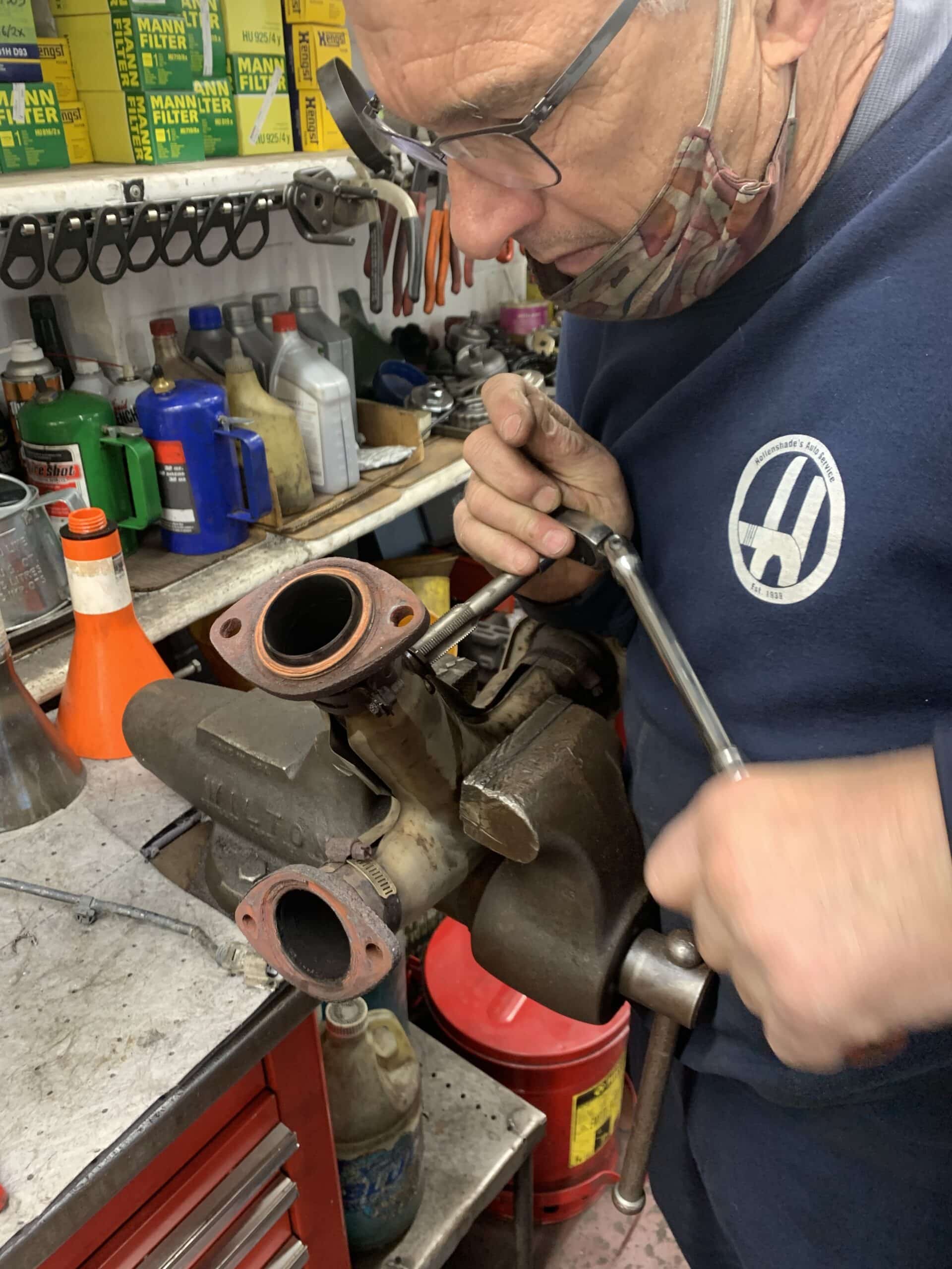
Removal & Installation
Oxygen sensors may be difficult to remove after they have been in a vehicle for a long time. A few techniques can help make the job easier. First, use the proper removal/installation tool. Second, it is helpful to apply some type of penetrating oil to the sensor thread area. Be careful not to get any on the upper part of the sensor where reference air enters. Third, sensors are easier to remove from a warm exhaust than from a cold one. Be careful not to get the temperature so high that it will cause burns or other dangers. Working the sensor back and forth may help remove it without damaging the threads.
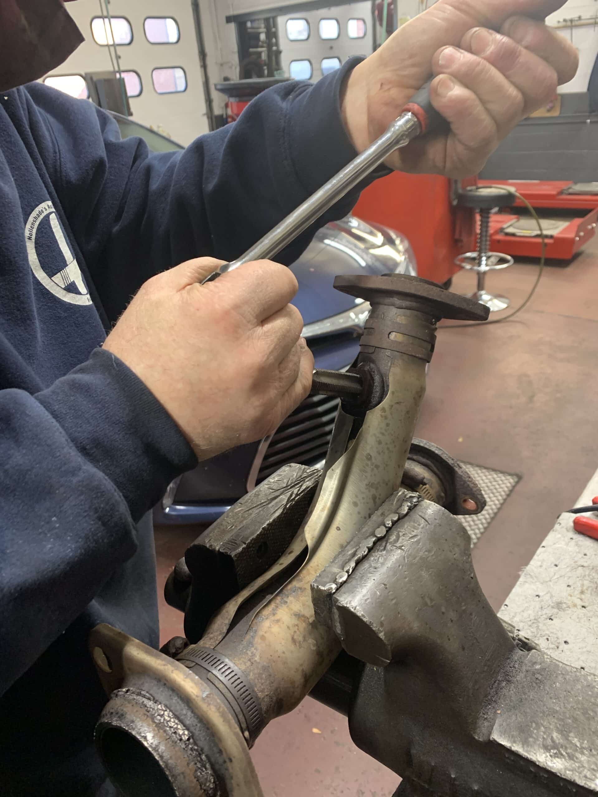
Replace the anti-seize compound on the threads when you put the sensor back in the vehicle. You also need to replace the seat gasket. Copper based anti-seize compounds, like those found in other automotive applications, work well with oxygen sensors.
Whether it is a new part or a reinstallation, install the sensor to the manufacturer recommended torque. Low torque can cause the sensor to fall out while excessive torque can increase the chance of seizure upon removal. Exhaust manifold thread damage can result if you use excessive force. If a sensor is difficult to remove, it is best to consult an experienced local mechanic like Hollenshade’s before damaging the threads within the exhaust pipe or exhuast manifold.
Catalytic Converter Monitoring
When the converter is warmed up and operating correctly, the signal from the sensor behind the converter moves slowly. It is not unusual for the signal from this sensor to stay at either high voltage (greater than 0.8 volts) or a low voltage (less than 0.2 volts) for several seconds or even minutes. When it switches between high and low, the rate of change may be slow compared to the primary engine control oxygen sensor or air-fuel ratio sensor. All these indications are normal and are not a reason to replace the sensor. It is best that an experienced technician evaluates check engine light codes related to oxygen sensors.
Contact Hollenshade’s for Towson Auto Repair
Hollenshade’s Auto Service has experience evaluating air-fuel ratio and oxygen sensor issues for your vehicle. Our expert Towson mechanics can handle any auto repairs and offer only the most transparent rates. Contact us today to schedule an appointment.